Design for printing · SLS / SLA
SLS design guidelines
Walls, holes and clearances from Formlabs documentation for Nylon 12. These are starting points for model assessment; PA11, TPU and critical fits need separate checks.
See also: SLA design guidelines · prototypes for designers.
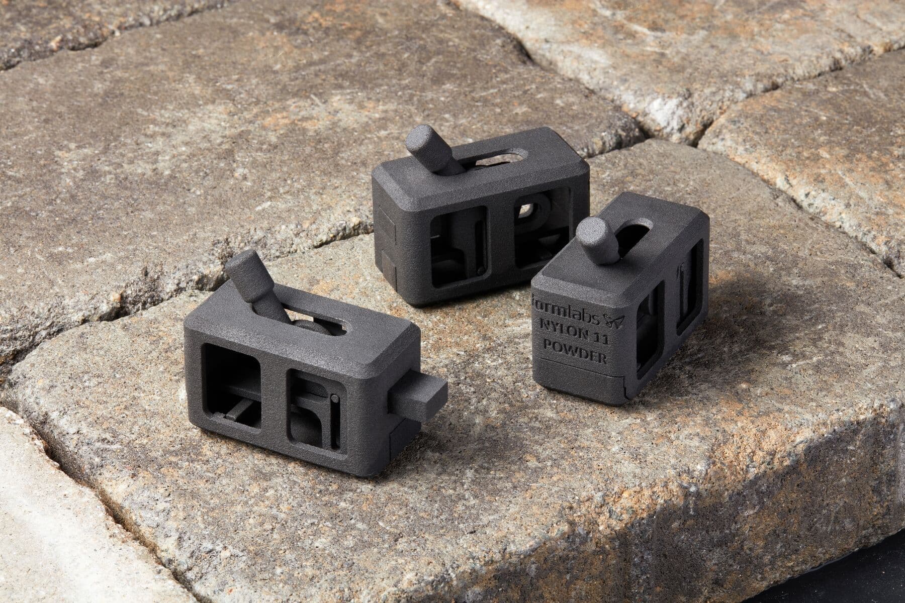
Nylon 12 starting values. See the tables for conditions and limitations.
- vertical wall, min.
- 0.6 mm
- hole, min. diameter
- 1.0 mm
- mounting clearance, small contact
- 0.2 mm
- calculator envelope, mm
- 159.8 × 159.8 × 295.5 mm
Do you need an explanation on how to apply these values in the model? Read the guide for designing parts for SLS printing.
Usable part size is smaller than the build chamber
Design data for Nylon 12
Build chamber
165 × 165 × 300 mm
Nominal printer chamber dimensions. Part size also depends on material, settings and layout.
Envelope used by the calculator, PA12
159.8 × 159.8 × 295.5 mm
The calculator uses the envelope from the Fuse Series guide. Current settings and rounded chamber corners are checked in PreForm. Larger models need assessment of orientation, splitting or another technology.
01
Walls and small features
4 values
Vertical and horizontal walls differ only in their orientation relative to the layer, not in whether something supports them.
Scroll the table sideways to see the remaining columns.
| Parameter | Value | Use and limitations |
|---|---|---|
| Vertical wall, minimum | 0.6 mm | At this thickness or below, the wall may warp or detach. Minimum thickness does not establish service strength. |
| Horizontal wall, minimum | 0.3 mm | Orientation relative to layers matters. At this thickness or below, the wall may warp or detach. |
| Pin, wire or rib | 0.8 mm | Recommended minimum diameter for a freestanding element. |
| Hole, minimum diameter | 1.0 mm | Holes below 1.0 mm in the X, Y, and Z axes may clog. The thicker the wall through which the hole passes, the less accurate its dimension. |
02
Text, logos and markings
4 values
Markings can be included in the model. Legibility depends on character height, line width, depth and orientation; very fine details may not resolve in the print.
Scroll the table sideways to see the remaining columns.
| Parameter | Value | Use and limitations |
|---|---|---|
| Raised text: letter height | 4.5 mm | Minimum text height; relief depth 0.3 mm. |
| Recessed text: letter height | 3.0 mm | Recessed goes lower than raised; groove depth 0.3 mm. |
| Raised detail: vertical surface | 0.35 mm | Minimum relief height; minimum feature width 0.4 mm. |
| Engraved detail: horizontal face | 0.1 mm | Minimum groove depth; minimum width 0.3 mm. |
03
Fits and print-in-place assemblies
4 values
Distinguish clearance for parts assembled after printing from clearance in integrated assemblies. Values apply to Nylon 12; PA11 and TPU need larger gaps and functional trials.
Scroll the table sideways to see the remaining columns.
| Parameter | Value | Use and limitations |
|---|---|---|
| Assembly clearance: surface below 20 mm² | 0.2 mm | Parts assembled after printing, with a small contact area. |
| Assembly clearance: surface above 20 mm² | 0.4 mm | The larger the contact area, the more clearance is needed for shrinkage. |
| Fully printed assembly: below 20 mm² | 0.3 mm | Moving parts printed in one build, with clearance for separation and cleaning. |
| Fully printed assembly: above 20 mm² | 0.6 mm | Too small clearance on a large surface will fuse the mechanism into a single solid. |
04
Hollow spaces and powder removal
3 values
A closed interior traps unsintered powder. Plan escape holes and cleaning access; hole diameter alone does not establish that the whole channel can be emptied.
Scroll the table sideways to see the remaining columns.
| Parameter | Value | Use and limitations |
|---|---|---|
| Powder drain hole diameter | 3.5 mm | Recommended minimum hole diameter for removing powder from the interior. |
| Number of powder drain holes | min. 2 | The manufacturer recommends at least two holes. Their placement and tool access need to suit the part interior. |
| Gap between individual details | 1.0 mm / 5.0 mm | Minimum 1.0 mm; recommended 5.0 mm to reduce thermal deformation between neighbouring parts. This describes our build layout, not your model. |
SLS design options
Without supports
Unsintered powder supports the part during printing. Orientation still affects warping, the surface and access for cleaning.
No mould-release draft angles
The process does not require wall draft angles for release from a mould. We design geometry for the part’s function and access for cleaning.
Undercuts and internal channels
They can be printed without supports. Allow access for powder removal; complex interiors may require extra finishing.
Assemblies in one build job
Moving assemblies can be made in one print. They need suitable clearances, powder access and functional checks after cleaning.
Rules for Form 4L
Form 4L · 353 × 196 × 350 mm
Orientation and supports are selected for the geometry; enclosed cavities need resin drainage and access for washing. Layers from 25 µm depend on the resin and print profile. Layer height does not specify the tolerance of the finished part.
Visible surface
Identify the visible surface. When orienting the model, we aim to limit support marks there; the sanding scope is agreed in the quotation.
Resin drainage
Hollow spaces need resin drainage, air access and access for washing. The number and position of holes depend on geometry and orientation.
Large concave surfaces
Concave surfaces can form a closed cup during printing. We check orientation and openings before preparing supports.
Washing and post-curing
We wash and post-cure the resin using the selected process. Cycles, drying and finishing are included in the schedule; TDS values refer to the manufacturer's specified tests.
Critical fit dimensions
Include a drawing with tolerances and describe assembly. We assess fits considering orientation, supports and dimensional changes during processing.
Production series
For larger series, we also compare SLS. Process selection is based on the model, material, finishing and working conditions.
We will confirm the design limits for your chosen resin and geometry when preparing the quote.
Sources
- Formlabs, Design specifications for 3D models (Fuse 1 generation), checked 12 October 2026
- Formlabs, "Fuse Series SLS Design Guide", March 2023
- Formlabs, "Calculating SLS Cost Per Part for Fuse Series 3D Printers", verified 31.08.2026
A design minimum does not guarantee the finished dimension or strength. Thin walls can warp during printing or finishing. Specify load, service duration and required fit; test fine features on a sample.
For printing
Checklist: model ready for SLS
17 checks to review while preparing a model. Reference values come from the manufacturer specifications; the checklist includes sources so you can verify them.
- Geometry
- Powder inside
- Fits
- Text and markings
- The file itself
Loading the form details. Please wait a moment.
Quick contact
Doubt about a specific detail?
Leave your phone number or email. We will discuss wall thickness, clearance and options for splitting a large model using your file.
Loading the form details. Please wait a moment.